
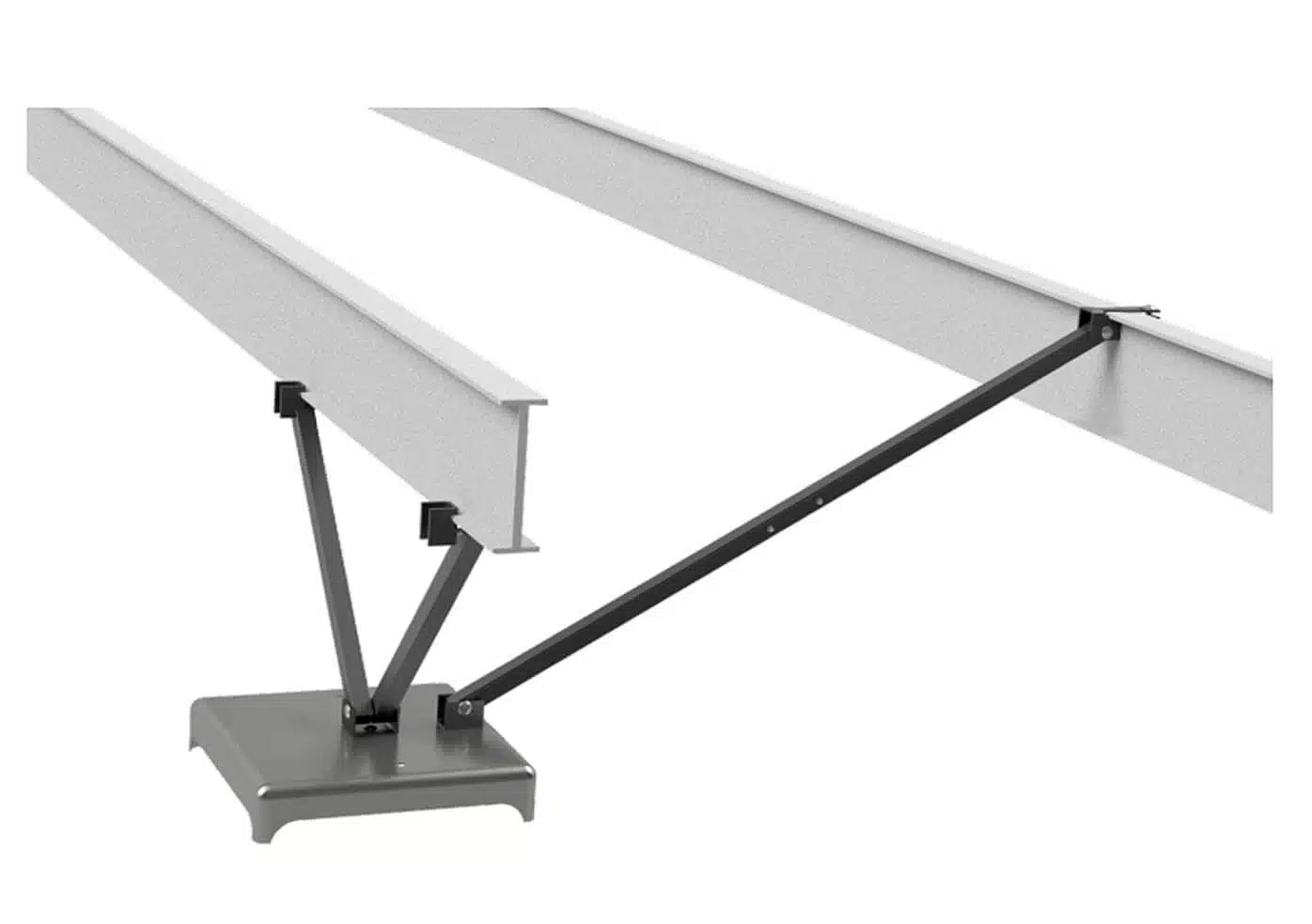
 Dirt Application · Ground Pan
Foundation Stabilizing Systems
ASFS 1100 IV
Pier Support System for Dirt Installations
The ASFS 1100 IV is an all-steel foundation system for dirt/soil installations using a ground pan. In listed HUD Wind Zone I–III applications, it can reduce or replace selected anchoring components when installed according to RAD-1371 and current installation instructions.
- Surface Dirt / soil (pan)
- Load rating See RAD-1371
- Soil class Up to 4B
- HUD Wind Zones I, II, III
Listed under RAD-1371. Longitudinal arm angles must fall between 40° and 60° for installation as instructed.
Pick your tube length
Sizing chart.
Match the block height under your home to the corresponding tube length. Each tube size covers a working pier-height range.
| Block Height | Pier Height Range | Tube Length |
|---|---|---|
| 1–2 | 14″ – 18″ | 20″ |
| 2–3 | 18″ – 25″ | 28″ |
| 3–4 | 24″ – 35″ | 39″ |
| 4–5 | 30″ – 40″ | 44″ |
| 5–6 | 36″ – 48″ | 54″ |
Confirm load ratings, pier-height limits, and installation angles against RAD-1371 and current Oliver installation instructions. Longitudinal arms must be installed at an angle between 40° and 60°.
Part numbers
Available configurations.
Part numbers for lateral-only and longitudinal+lateral systems in painted or galvanized finishes, with dry-set or wet-set installation options. Confirm final selection against RAD-1371 and current Oliver installation instructions.
| Protection | Arm Length | Finish | Dry Set (D) | Wet Set (W) |
|---|---|---|---|---|
| Lateral only | — | Painted | 1100ITCVD |
1100ITCVW |
| Lateral only | — | Galvanized | 1100ITCVDG |
1100ITCVWG |
| Longitudinal + Lateral | 20″ | Painted | 1100ICVD-20 |
1100ICVW-20 |
| Longitudinal + Lateral | 20″ | Galvanized | 1100ICVD-20G |
1100ICVW-20G |
| Longitudinal + Lateral | 28″ | Painted | 1100ICVD-28 |
1100ICVW-28 |
| Longitudinal + Lateral | 28″ | Galvanized | 1100ICVD-28G |
1100ICVW-28G |
| Longitudinal + Lateral | 39″ | Painted | 1100ICVD-39 |
1100ICVW-39 |
| Longitudinal + Lateral | 39″ | Galvanized | 1100ICVD-39G |
1100ICVW-39G |
| Longitudinal + Lateral | 44″ | Painted | 1100ICVD-44 |
1100ICVW-44 |
| Longitudinal + Lateral | 44″ | Galvanized | 1100ICVD-44G |
1100ICVW-44G |
| Longitudinal + Lateral | 54″ | Painted | 1100ICVD-54 |
1100ICVW-54 |
| Longitudinal + Lateral | 54″ | Galvanized | 1100ICVD-54G |
1100ICVW-54G |
Florida installations require G120 galvanized components. Confirm part #1101V and the required configuration against current Oliver installation instructions and applicable state/local requirements.
Dry-set (D) part numbers are for installations without pre-poured concrete around the pan. Wet-set (W) part numbers are designed to be cast into wet concrete pours.
Installation
Instructions & videos.
Use the written installation instructions with RAD-1371 and applicable installation requirements. The walkthrough video is a visual reference only.
PDF · Written instructions
ASFS Installation Instructions
Full step-by-step installation guide for the ASFS 1100 series. Includes torque values, anchor angles, and clearance requirements.
Video · Reference only
Installation Walkthrough
Visual walkthrough showing the ASFS install sequence. Not a substitute for the written installation instructions.
Need installation support?
Call Oliver Technologies for compatibility questions, quotes, or installation guidance.