Buyers’ Guide
Manufactured Home Setup Material Buyers’ Guide
The following buyers’ guide will help you in finding the best product for your needs.
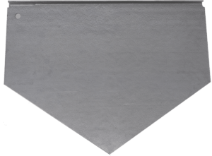
Determining What Size ABS Pad or Footing to Use
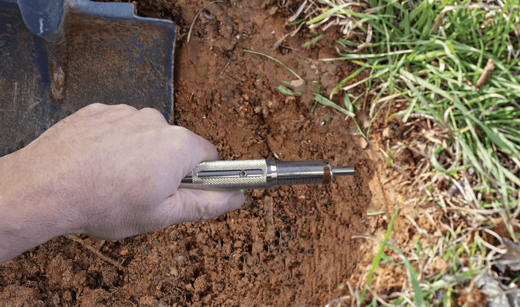
How to Determine Soil Density Using a Penetrometer
When installing a manufactured home, it is important to determine the soil density where the footings will be located under the home. This is done by using a soil penetrometer.
Pocket Penetrometer · Part # SOILTESTOnce you have determined the pier load requirements by using the home manufacturer’s setup manual or HUD code 3285, you can now choose the most cost effective footing or pad to set the home. There are many ABS Pads to choose from depending upon the soil and load requirements.
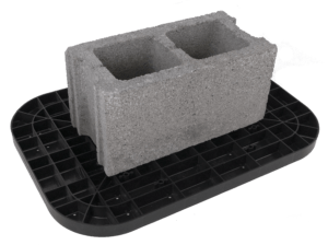
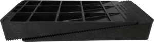
ABS Pads
Building the Piers
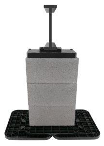
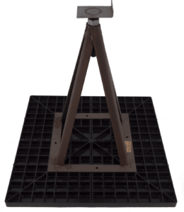
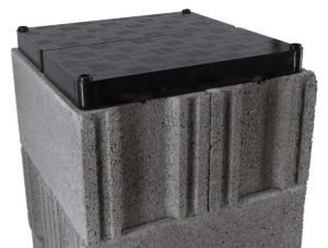
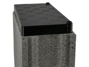
Once you have determined the proper size pad, you will need to build your piers using either steel piers or concrete blocks. Steel piers are available in several heights and two head options. When using concrete block for piers, cap boards and wedges provide the proper support height.
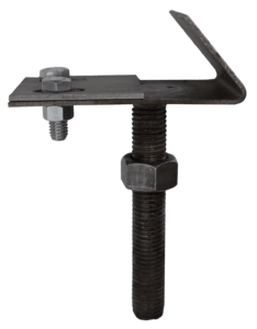
Steel Piers & Heads
Up to 6,000 lbs

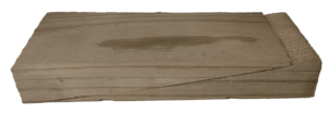
Cap Boards
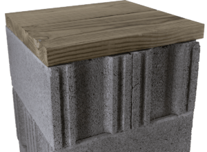
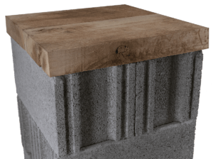
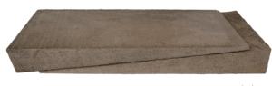
Wedges
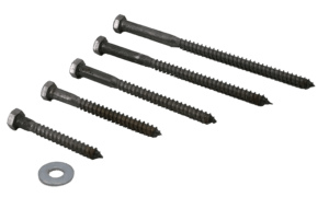
Determining the Proper Anchors to Use
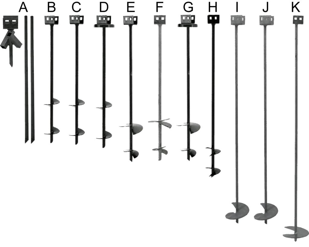
There are a couple of types and several size anchors used when securing down a manufactured home or other building. For dirt installation, you will need to use a torque probe to determine the proper size earth auger anchor needed.
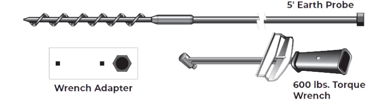
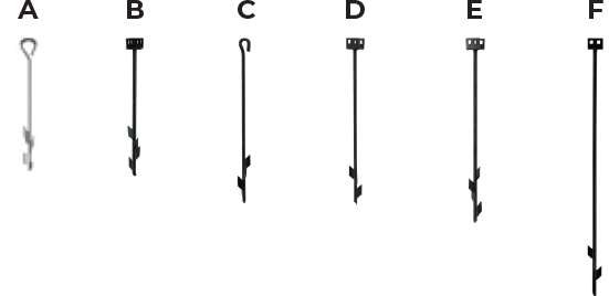
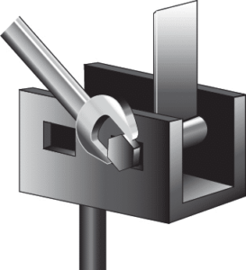
Torque Probe
The Torque Probe is needed to determine the soil classification where the anchor’s helix will be located in the ground. Use the Soil Classification Chart below to see recommended anchors for each soil condition. Once you have determined the proper size anchor from your Torque Probe results, refer to the home manufacturer’s setup manual or HUD code 3285 to choose the proper anchor spacing needed.
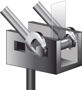
Torque Probe Instructions
- Place the tip of the earth probe in the ground, closest to where you intend to install the anchor. Rotate the probe clockwise using a 15/16″ hex socket or electric drive machine.
- Rotate the probe into the soil until you have reached the depth equal to the length of the anchor you intend to install.
- Place the wrench adapter on the torque wrench and insert the hex portion of the wrench adapter onto the earth probe.
- Steadily rotate the torque wrench on the probe while supporting the probe with the opposite hand. (Do not exceed 600 inch lbs.)
- While rotating clockwise, view the torque wrench test value.
- Use the Soil Classification Chart below to determine the proper anchor needed for the soil conditions.
- If test results do not match the anchor for that depth, rotate the probe to the next anchor depth and check reading. Repeat until probe reading matches anchor length for depth of reading.
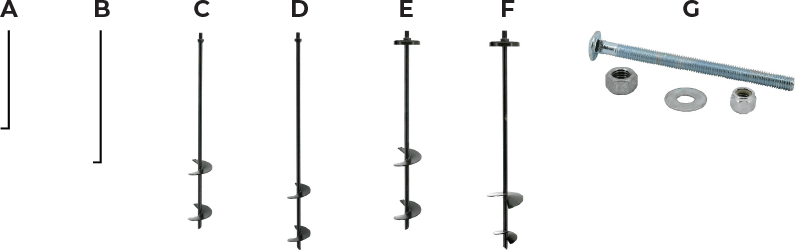
Soil Classification Chart
Use the chart below to choose the proper earth auger anchor for each soil classification.
| Soil Class & Test Value | Product # | Height | Width | Helix & Width | Type |
|---|---|---|---|---|---|
| 1 - N/A (solid rock) | (A) OT30CDP | 30″ | 3/4″ | 1 - 6″ | Painted |
| 2 - 550 inch lbs. or more | (B) OT3044AP | 30″ | 5/8″ | 2 - 4″ | Painted |
| 2 - 550 inch lbs. or more | (C) OT3044BP | 30″ | 3/4″ | 2 - 4″ | Painted |
| 2 - 550 inch lbs. or more | (D) OT3044BPC | 30″ | 3/4″ | 2 - 4″ | Painted, Cap Welded |
| 3 - 350 to 550 inch lbs. | (E) OT3646BP | 36″ | 3/4″ | 1 - 4″ & 1 - 6″ | Painted |
| 3 - 350 to 550 inch lbs. | (F) OT3646BG | 36″ | 3/4″ | 1 - 4″ & 1 - 6″ | Galvanized |
| 3 - 350 to 550 inch lbs. | (G) OT3646BPC | 36″ | 3/4″ | 1 - 4″ & 1 - 6″ | Painted, Cap Welded |
| 3 - 350 to 550 inch lbs. | (H) OT4244BP | 42″ | 3/4″ | 2 - 4″ | Painted |
| 4a - 276 to 350 inch lbs. | (E) OT3646BP | 36″ | 3/4″ | 1 - 6″ | Painted |
| 4a - 276 to 350 inch lbs. | (F) OT3646BG | 36″ | 3/4″ | 1 - 6″ | Galvanized |
| 4a - 276 to 350 inch lbs. | (H) OT4244BP | 42″ | 3/4″ | 2 - 4″ | Painted |
| 4a - 276 to 350 inch lbs. | (I) OT486A | 48″ | 5/8″ | 1 - 6″ | Galvanized |
| 4a - 276 to 350 inch lbs. | (J) OT486B | 48″ | 3/4″ | 1 - 6″ | Galvanized |
| 4b - 175 to 275 inch lbs. | (K) OT607B | 60″ | 3/4″ | 1 - 7″ | Galvanized |
* Contact us about additional sizes that may be available
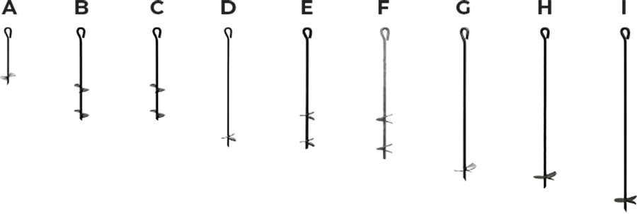
Multi-Purpose Anchors
If you need anchors for swing sets, trampolines, trees, carports and more, choose from the anchors below.
Multi-Purpose Barbed Drive Anchors
| Product # | Height | Width | Barb | Barb Width | Type |
|---|---|---|---|---|---|
| 3424EAB-B (Eye) | 24″ | 3/4″ | 4 | 2″ | Painted |
| OT24BBP (Rock) | 24″ | 3/4″ | 4 | 2″ | Painted |
| 5830EAB-B (Eye) | 30″ | 5/8″ | 4 | 2″ | Painted |
| OT30BBP (Rock) | 30″ | 5/8″ | 4 | 2″ | Painted |
| OT36BBP (Rock) | 36″ | 3/4″ | 4 | 2″ | Painted |
| OT48BBP (Rock) | 48″ | 3/4″ | 4 | 2″ | Painted |
* Contact us about additional sizes that may be available
Multi-Purpose Eye Auger Anchors
| Product # | Height | Width | Barb | Barb Width | Type |
|---|---|---|---|---|---|
| 1215EAB | 15″ | 1/2″ | 1 | 4″ | Painted |
| 342444EAB | 24″ | 3/4″ | 2 | 4″ | Painted |
| 582444EAB | 24″ | 3/4″ | 2 | 4″ | Painted |
| 1230EAB | 30″ | 1/2″ | 1 | 4″ | Painted |
| 583044EAB | 30″ | 5/8″ | 2 | 4″ | Painted |
| 343644EAB | 36″ | 3/4″ | 2 | 4″ | Painted |
| 3448EAB | 36″ | 3/4″ | 1 | 6″ | Painted |
| 3440EAB | 40″ | 3/4″ | 1 | 6″ | Painted |
| 3442EAB | 42″ | 3/4″ | 1 | 6″ | Painted |
* Contact us about additional sizes that may be available
Shed & Other Building Anchors
| Product # | Height | Width | Barb | Barb Width | Type |
|---|---|---|---|---|---|
| OT3044APMP (No Cap) | 30″ | 5/8″ | 2 | 4″ | Painted |
| OT3644APMP (No Cap) | 36″ | 5/8″ | 2 | 4″ | Painted |
| OT3044BPCMP (Cap) | 30″ | 3/4″ | 2 | 4″ | Welded & Painted |
| OT3646BPCMP (Cap) | 36″ | 3/4″ | 2 | 4″ & 6″ | Welded & Painted |
* Contact us about additional sizes that may be available
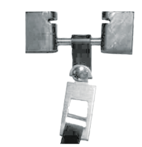
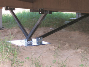
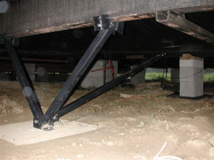
Anchor Stabilization Devices
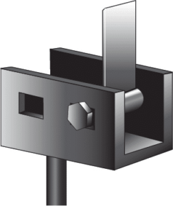
Stabilizing devices are used when the anchor is connected to the main chassis beam and is pulled at a 45 degree angle or cross strapping.
Determining the Proper Tie Down Connectors & Straps
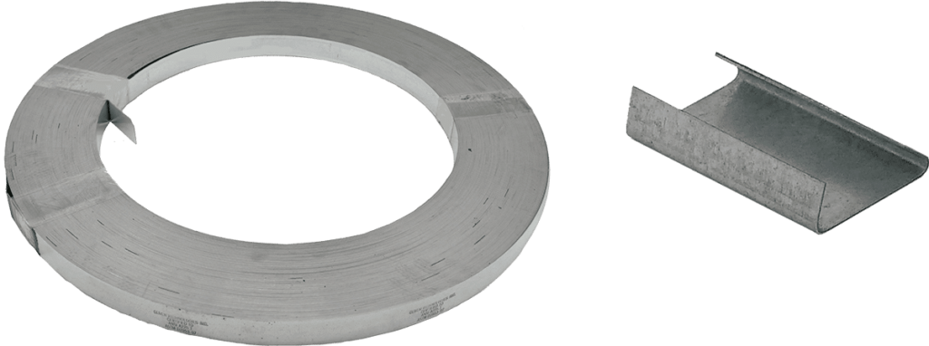
When securing a home, there are several areas that need to be tied down to make the home safe. Now that you have chosen the proper anchors and stabilizing devices, you will need to determine the attachment connectors on the frame or side wall, as well as longitudinal protection and the proper strap lengths. We have several options to choose from.
Tie Down Connectors
Longitudinal Connectors
When homes are equipped with pre-installed sidewall and/or longitudinal brackets, you have a couple of choices.
-
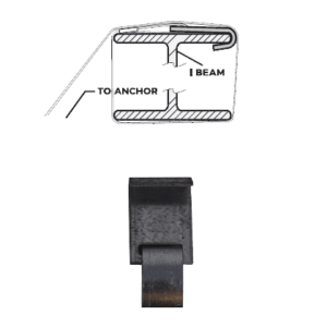
 Longitudinal I-Beam ConnectorsPart # OTLTK · Quick Connector sold separately
-
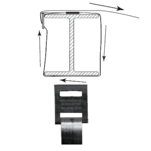
 Sidewall BracketPart # OTSWB
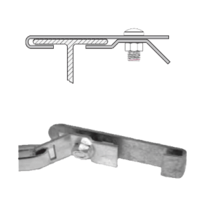
Attaching the Strap
Galvanized Split Bolt
5/8″ x 3″ x 5/8″ square shoulder with hexagon head
Part # OT S/B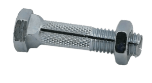
-
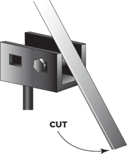 1
1Insert split bolt into anchor head, attach loosely. Pull strap past bolt and cut strap leaving approximately 12″ of strap to wrap onto bolt.
-
 2
2Insert the strap end into the slot in bolt until flush with opposite side of bolt.
-
 3
3Using a 15/16″ wrench or socket, turn the bolt, winding the strap so that a minimum of four to five complete turns are made and the strap is tensioned so the anchor is firmly against the stabilizing device in direction of pull. All slack must be removed.
-
 4
4Hold the bolt under tension while tightening the nut, drawing the head of the bolt into the recess. Continue to tighten the nut until securely fastened.
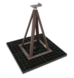
Foundation Stabilization Systems
An innovative alternative to conventional anchors is our All Steel Foundation Systems (ASFS). These systems eliminate the need for most anchors in Wind Zone 1. In Wind Zones 2 & 3, ASFS eliminates the need for diagonal frame ties, stabilizer plates and anchors required for longitudinal protection. ASFS can be used in all soil classes up to 4B. All Steel Foundation Systems are available with or without a pier support.
All Steel Foundation Systems With Pier Support
Supporting the Perimeter of the Home or Building
There are several door/window and perimeter pier support options. Typically perimeter supports use footings installed at or below frost depth. Oliver Technologies offers a few alternative perimeter support options that are not affected by frost heave, making your perimeter support installations fast and easy.
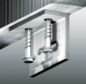
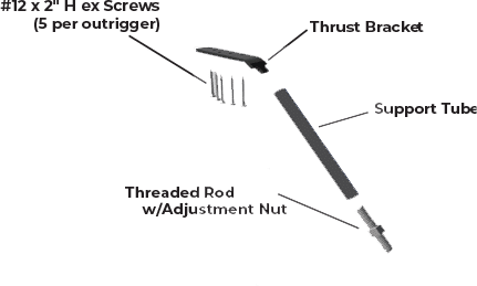
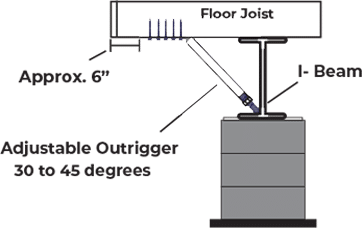
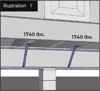
Adjustable Outriggers
Maximum working load 1,740 lbs
The Adjustable Outrigger has been designed to replace perimeter piers with a maximum working load of 1,740 lbs. Refer to the installation manual or home manufacturer for roof loads, pier loads and location of perimeter piers.
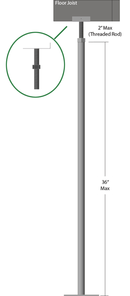
EZ Piers
Maximum working load 4,000 lbs
The EZ Pier is another replacement for the conventional perimeter support. It can be used for pier heights up to 39″ and features a 2″ adjustment. The pipe can be cut-to-fit for shorter heights.
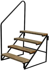
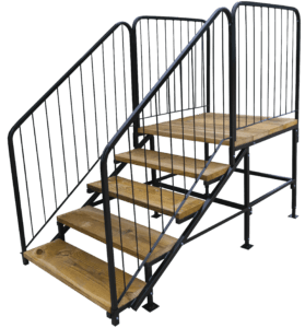
Choosing the Right Steps
Our Wood/Metal Steps feature painted black metal frames and treated treads. They are available in several heights, platform depths and your choice of Standard or IRC compliant steel handrails.